How to Choose Dynamic Compaction Equipment in 2026?
Choosing Dynamic Compaction Equipment in 2026 starts with the ground, not the machine brochure. Soil type, loose-layer depth, groundwater, and nearby structures all affect the right setup. A crane-mounted system may suit a large, open site, while restricted access can change the practical options. Small details matter. A soft haul road, for example, can limit crane movement before compaction even begins.
Compare rammer weight, drop height, operating range, and production targets against a geotechnical assessment. Check the crane’s rated capacity at the actual working radius, not just its headline lifting figure. Ask how the control system records drops, energy, and coverage; usable records help teams review progress and identify inconsistent areas. Reliability counts, too. Look at service access, parts availability, operator training, and the time required to reposition equipment between points. These factors shape real output more than a specification sheet suggests.
There is no universal best choice. A heavier rammer is not automatically better if vibration limits, soil conditions, or crane capacity make it unsuitable. Get project-specific advice from qualified geotechnical and equipment professionals, and confirm monitoring requirements before work starts. A little uncertainty remains until site conditions are verified. That is normal. The aim is to select equipment that delivers the required improvement safely, consistently, and within the project’s constraints—not simply the largest machine available.
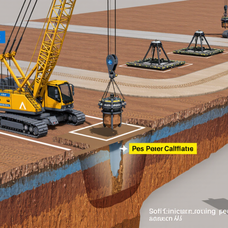
Assess Soil Type and Improvement Depth Before Choosing Dynamic Compaction Equipment
How to Choose Dynamic Compaction Equipment in 2026?
Assess Soil Type and Improvement Depth Before Choosing Dynamic Compaction Equipment
Soil conditions should guide equipment selection before hammer weight or crane capacity. Dynamic compaction generally suits loose granular deposits, reclaimed ground, and some uncontrolled fills. It is less predictable in saturated, cohesive soils, where pore pressure can slow improvement. Check borehole logs, groundwater levels, and grading records. A sandy fill with gravel behaves differently from wet silt, even at the same depth.
The FHWA Ground Modification Methods Reference Manual (FHWA-HIF-13-046, 2017) describes an empirical depth estimate: D = n√(WH), where D is metres, W is drop mass in tonnes, and H is drop height in metres. The coefficient n commonly ranges from about 0.3 to 0.8, depending on soil and site conditions. Treat that range as an initial design screen. It is not a guarantee. Trial drops and field measurements should refine the estimate.
Match the equipment to the required treatment depth, working platform, and nearby structures. For example, a 10-tonne weight dropped 15 metres gives a different energy profile from a heavier weight dropped lower. Verify crane reach, cycle time, and safe access before mobilization. Monitor settlement and vibration during test sections. In practice, schedules can tempt teams to skip this step. I would not. Even a sound calculation can miss buried debris or variable fill.
Match Crane Capacity to 10–40 t Pounders and 10–30 m Drop Heights
Choosing dynamic compaction equipment starts with the pounder’s mass and the crane’s actual working radius. A 10–40 t pounder lifted 10–30 m demands more than adequate nominal capacity. Include the hook block, lifting gear, boom configuration, and operating radius in the lift-chart check. Small details matter.
The Federal Highway Administration’s 1995 Dynamic Compaction report describes typical tamper weights of about 10–30 tonnes and drop heights of 10–30 m. A 40 t pounder sits above that reported common range, so confirm the project’s lift plan rather than treating it as routine. At the site, check the crane’s level, ground support, and clearance beneath overhead services. Capacity falls as working radius increases. That assumption deserves checking.
Match each lift to the planned grid and production cycle. A crane that can raise the pounder may still be inefficient if boom reach or repositioning slows the sequence. Record the heaviest lifted assembly and the radius at each drop point. Recheck those figures when site conditions change; muddy access or a shifted working platform can alter crane setup. Allow time for inspection, too. Real sites are rarely perfect.
Compare Impact Energy Across the Typical 100–1,200 t·m Operating Range
In 2026, compare dynamic compaction equipment by impact energy, not hammer mass alone. The usual 100–1,200 t·m range describes nominal energy per drop: mass multiplied by drop height. It is a starting point, not a guarantee of ground improvement. Two rigs with similar ratings can deliver different results because of lifting setup, operating cycle, and site conditions.
At roughly 100–300 t·m, equipment may suit shallower treatment or sites where tighter control matters. The 300–600 t·m band can offer a practical middle ground for broader improvement. Around 600–1,200 t·m, higher energy may help address deeper or denser ground, but it demands a rig and crane suited to the load and drop height.
There is no perfect cutoff. Soil type, groundwater, layer thickness, and nearby structures can shift the choice considerably.
Check the full operating setup. A heavy tamper needs reliable lifting capacity, suitable rigging, and a stable working platform. Field trials can reveal whether the planned drop pattern produces the required improvement without excessive vibration. Numbers need context. A high rating may look impressive on paper, yet prove inefficient if the soil response is poor or the working area is restricted. Confirm energy per blow, cycle time, and monitoring requirements with a qualified geotechnical team before selection.
Select Rig Mobility, Winch Control, and Safety Features for Site Conditions
How to Choose Dynamic Compaction Equipment in 2026?
Match rig mobility to the ground, not just the site plan. On soft or saturated soils, check track pressure and turning space before mobilization. A rig that reaches the work area but cannot reposition safely will slow production. FHWA’s Soils and Foundations Reference Manual describes typical dynamic-compaction drop weights of about 5–30 tonnes and drop heights of 10–30 metres. These ranges help frame equipment capacity, but actual selection depends on soil conditions and the approved treatment design.
Winch control should make each drop repeatable. Look for clear height indicators, responsive braking, and controls that let operators stay outside the impact zone. Test them under realistic conditions: a muddy cab step or poor visibility can change how easily the crew monitors the hammer. A specification sheet can still mislead. Ask how the rig handles uneven ground and repeated cycles, not only its maximum lift.
Safety features matter as much as output. Check emergency stops, guarding, wire-rope inspection access, and communication between the operator and ground crew. OSHA guidance calls for equipment inspections and safe operating practices; the BLS reported 1,075 fatal work injuries among construction and extraction occupations in 2023. That figure is not specific to compaction, but it reinforces the need to assess site hazards. Some details are easy to miss. Revisit the setup after rain, when access and ground stability may have changed.
Verify Compaction with CPT or SPT Results Before Finalizing Equipment Specs
How to Choose Dynamic Compaction Equipment in 2026?
Verify Compaction with CPT or SPT Results Before Finalizing Equipment Specs
A heavier tamper is not automatically the better choice. Start with ground conditions and the improvement depth, then use CPT or SPT results to check whether the equipment can meet the project criteria. The FHWA Ground Improvement Methods Reference Manual (FHWA-NHI-16-027, 2017) describes the preliminary depth estimate D = n√(WH), relating treatment depth to tamper weight and drop height. It is a planning estimate, not proof of achieved compaction. Local soil conditions matter.
Before and after treatment, compare CPT cone resistance (qc) or corrected SPT blow counts (N60) at consistent test locations and depths. Look for weak layers that remain below the target, not just better readings near the surface. Record groundwater conditions and test methods too; otherwise, a change in results may reflect testing differences rather than improvement. A few scattered tests can miss variability. That is an uncomfortable limitation, but worth addressing.
Tips: Set acceptance thresholds before tendering equipment. Use a trial area to adjust drop energy, grid spacing, and passes, then verify the response with repeat CPT or SPT testing. If results fall short, revise the treatment plan before locking in final equipment specifications.